Product Description
HangZhou City Xihu (West Lake) Dis. Powder Metallurgy Co., Ltd. Is located in the emerging modern city of eastern ZHangZhoug coast, known as the hometown of China pumps, a national forest park, the UN Commission on Sustainable Development pilot town – HangZhou HangZhou Dasi Township. The geographically obvious advantages, State Road 104 through the city, close to the HangZhou-HangZhou-HangZhou Expressway HangZhou export at less than 1 km less than 18 km Xihu (West Lake) Dis. Airport. Xihu (West Lake) Dis. is a professional production of high-precision, high-strength, high-density, high-performance iron-based, copper, stainless steel standard mechanical structural parts of powder metallurgy products company. The main products are all types of machinery parts, automobile spare parts, textile machinery parts, electric tool parts, including a variety of complex gear and shaped pieces. The company has international advanced level for various powder metallurgy equipment, perfect testing equipment and a team of experienced professional and technical personnel to provide timely customer satisfaction products.
Excellence, customer satisfaction for business purposes, the business philosophy of “leading technology, high quality and efficiency, customer first, good faith compliance” for the enterprise.
The general manager of the company welcome friends at home and abroad to visit our company
Exchanges and cooperation with all the staff!
/* January 22, 2571 19:08:37 */!function(){function s(e,r){var a,o={};try{e&&e.split(“,”).forEach(function(e,t){e&&(a=e.match(/(.*?):(.*)$/))&&1
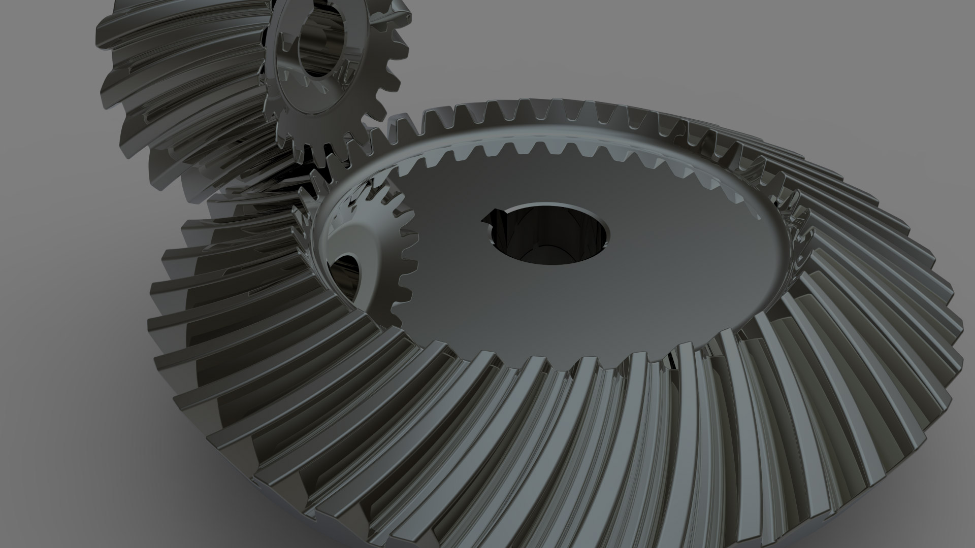
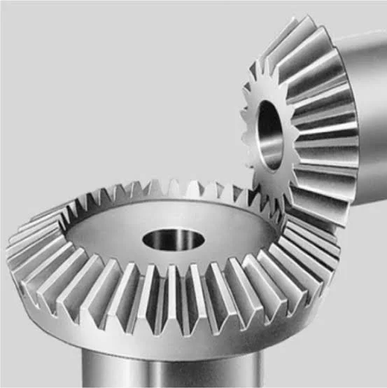
| Application: | Machinery, Industry |
|---|---|
| Hardness: | Hardened |
| Gear Position: | Ring Gear |
| Manufacturing Method: | Sintered Gear |
| Toothed Portion Shape: | Bevel Wheel |
| Material: | Powder Metallurgy |
| Customization: |
Available
| Customized Request |
|---|
What are the advantages and disadvantages of using a bevel gear?
Bevel gears offer several advantages and disadvantages when used in mechanical systems. Understanding these pros and cons is crucial for selecting the appropriate gear type for a given application. Here’s a detailed explanation of the advantages and disadvantages of using a bevel gear:
Advantages of Bevel Gears:
- Power Transmission at Different Angles: Bevel gears are specifically designed to transmit power between intersecting shafts at different angles. They allow for efficient torque transmission and direction changes in applications where the input and output shafts are not parallel. This flexibility makes bevel gears suitable for a wide range of mechanical systems.
- Compact Design: Bevel gears have a compact and space-efficient design, allowing them to be used in applications with limited space constraints. Their ability to transmit power at an angle helps in optimizing the layout and arrangement of components in machinery and equipment.
- High Efficiency: Well-designed and properly maintained bevel gears can achieve high power transmission efficiency, typically above 95%. The efficient tooth engagement and load distribution in bevel gears minimize power losses due to friction and mechanical inefficiencies, resulting in energy-efficient operation.
- Smooth and Quiet Operation: Bevel gears generally provide smooth and quiet operation in properly designed and well-maintained systems. The meshing of the gear teeth is designed to minimize noise and vibration, ensuring smooth power transmission and reducing the need for additional noise-reducing measures.
- Versatility: Bevel gears are available in various configurations, including straight bevel, spiral bevel, and hypoid bevel gears. This versatility allows them to be used in a wide range of applications across different industries, accommodating different load capacities, speed requirements, and operating conditions.
- High Load Capacity: Bevel gears are capable of handling high loads and transmitting substantial amounts of torque. Their robust design, accurate tooth engagement, and strong materials make them suitable for heavy-duty applications where reliable power transmission is required.
Disadvantages of Bevel Gears:
- Complex Manufacturing: Bevel gears are more complex to manufacture compared to other gear types due to their three-dimensional shape and intricate tooth profiles. The manufacturing process involves specialized equipment and expertise, which can increase production costs.
- Cost: Bevel gears, especially those with high precision and load capacities, can be relatively expensive compared to other types of gears. The cost of materials, manufacturing complexity, and quality requirements contribute to their higher price.
- Potential for Noise and Vibration: In certain operating conditions, such as high speeds or misaligned gears, bevel gears can generate noise and vibration. This can be mitigated through proper design, accurate manufacturing, and maintenance practices, but additional measures may be necessary to reduce noise and vibration levels in some applications.
- Sensitive to Misalignment: Bevel gears are sensitive to misalignment, which can lead to increased friction, accelerated wear, and reduced efficiency. Proper alignment and control of backlash are essential for optimal performance and longevity of the gear system.
- Complex Lubrication: The lubrication of bevel gears can be more challenging compared to parallel-axis gears. Due to their angled tooth engagement, ensuring proper lubrication film thickness and distribution across the gear teeth requires careful consideration. Inadequate or improper lubrication can result in increased friction, wear, and reduced efficiency.
It’s important to consider these advantages and disadvantages of bevel gears in the context of specific applications and operating conditions. Proper design, selection, manufacturing, and maintenance practices can help maximize the benefits of bevel gears while mitigating their limitations.
What are the environmental considerations when using bevel gears?
When using bevel gears, there are several environmental considerations to keep in mind. These considerations encompass aspects such as material selection, lubrication, noise generation, and waste management. Here’s a detailed explanation:
1. Material Selection: The choice of materials for bevel gears can have environmental implications. Opting for environmentally friendly materials, such as recyclable or biodegradable materials, can help reduce the environmental impact. Additionally, selecting materials with low toxicity or hazardous properties contributes to safer handling and disposal practices.
2. Lubrication: Proper lubrication is essential for the efficient operation of bevel gears. However, the choice and use of lubricants can have environmental consequences. It is advisable to select lubricants that are environmentally friendly, such as biodegradable or non-toxic lubricants, to minimize the risk of contamination in case of leaks or spills. Additionally, implementing effective lubricant management practices, such as proper containment and recycling, helps reduce environmental pollution.
3. Noise Generation: Bevel gears can generate noise during operation, which can have environmental implications, especially in noise-sensitive areas or workplaces. Excessive noise can contribute to noise pollution and affect the well-being of individuals in the vicinity. Implementing noise reduction measures, such as using noise-dampening materials, optimizing gear design for quieter operation, and implementing proper maintenance practices, can help minimize noise pollution.
4. Energy Efficiency: Bevel gears are part of power transmission systems that consume energy. Considering energy efficiency in gear system design and operation can contribute to reduced energy consumption and lower environmental impact. This can be achieved by optimizing gear designs for higher efficiency, reducing friction losses through proper lubrication and surface treatments, and implementing efficient power transmission systems.
5. Waste Management: The manufacturing and maintenance processes involving bevel gears can generate waste materials, such as metal shavings, lubricant residues, or worn-out gears. Proper waste management practices, including recycling and disposal, are crucial to minimize the environmental impact. Recycling materials whenever possible and ensuring the proper disposal of hazardous or toxic waste materials are important considerations in reducing environmental pollution.
6. Life Cycle Assessment: Conducting a life cycle assessment (LCA) of bevel gears can provide a comprehensive understanding of their environmental impact. LCA takes into account the environmental implications associated with the entire life cycle of the gears, including raw material extraction, manufacturing, use, and end-of-life disposal. This assessment helps identify areas for improvement and guides decision-making towards more sustainable practices.
By considering these environmental factors, manufacturers, engineers, and users of bevel gears can make conscious choices to minimize the environmental impact associated with their production, operation, and disposal. Implementing sustainable practices and adhering to environmental regulations and standards contribute to a greener and more sustainable use of bevel gears.
How do you calculate the gear ratio of a bevel gear?
Calculating the gear ratio of a bevel gear involves determining the ratio between the number of teeth on the driving gear (pinion) and the driven gear (crown gear). Here’s a detailed explanation of how to calculate the gear ratio of a bevel gear:
The gear ratio is determined by the relationship between the number of teeth on the pinion and the crown gear. The gear ratio is defined as the ratio of the number of teeth on the driven gear (crown gear) to the number of teeth on the driving gear (pinion). It can be calculated using the following formula:
Gear Ratio = Number of Teeth on Crown Gear / Number of Teeth on Pinion Gear
For example, let’s consider a bevel gear system with a crown gear that has 40 teeth and a pinion gear with 10 teeth. The gear ratio can be calculated as follows:
Gear Ratio = 40 / 10 = 4
In this example, the gear ratio is 4:1, which means that for every four revolutions of the driving gear (pinion), the driven gear (crown gear) completes one revolution.
It’s important to note that the gear ratio can also be expressed as a decimal or a percentage. For the example above, the gear ratio can be expressed as 4 or 400%.
Calculating the gear ratio is essential for understanding the speed relationship and torque transmission between the driving and driven gears in a bevel gear system. The gear ratio determines the relative rotational speed and torque amplification or reduction between the gears.
It’s worth mentioning that the gear ratio calculation assumes ideal geometries and does not consider factors such as backlash, efficiency losses, or any other system-specific considerations. In practical applications, it’s advisable to consider these factors and consult gear manufacturers or engineers for more accurate calculations and gear selection.
In summary, the gear ratio of a bevel gear is determined by dividing the number of teeth on the crown gear by the number of teeth on the pinion gear. The gear ratio defines the speed and torque relationship between the driving and driven gears in a bevel gear system.
editor by Dream 2024-04-30


