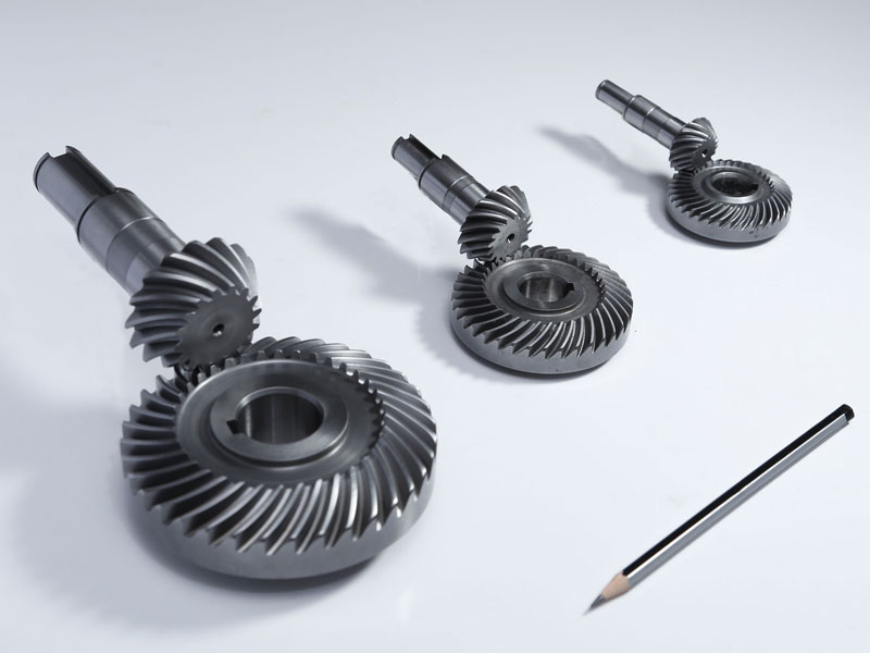
Product Description
We are a professional company in bulk material handling, transportation, storage, processing, accessory equipment design, integration and manufacturing. We can provide a complete set of solutions. Thank you for reading the information and welcome to purchase! Welcome to agent distribution!
Brief introduction of the company’s manufacturing capacity
The company’s headquarters, technology and sales are located in Lingang New Area of China (ZheJiang ) pilot free trade zone,The company’s manufacture base is located in Xihu (West Lake) Dis. county, ZHangZhoug Province, which is known as “the most beautiful county in China”. It is 65 kilometers away from HangZhou city and 60 kilometers away from Qiandao Lake. The transportation to Xihu (West Lake) Dis. county from other places is very convenient. No matter by railway, highway or waterway. The manufacture base has a total plant area of around 30000 square CHINAMFG and workshop is equipped with more than 300 sets of various advance manufacture equipment, including 20 sets of CNC precision vertical lathe MODEL: SMVTM12000×50/150, CNC vertical lathe MODEL:DVT8000×30/32, CNC horizontal lathe, MODEL: CK61315×125/32, CNC horizontal lathe MODEL:CK61200×80/32, CNC Grounding boring and milling machine MODEL:TJK6920,etc.Most of the parts are machined by using CNC machine equipment. Theis is a hot treatment CHINAMFG with size 10.5m×8m×8m. The manufacture base also equipped with lifting capacity of 25t, 50t, 100t, 200t overhead crane to handle heavy workpiece and assembly work.
Metalworking equipment
| Name of equipment | Model number | Quantity | SCOPE of application | |
| A | Lathes | |||
| 1 | Vertical Lathe | Numerical control | 1 | Φ 12000 |
| 2 | Vertical Lathe | Numerical control | 1 | Φ 8000 |
| 3 | Vertical Lathe | 1 | Φ 1600 | |
| 4 | Vertical Lathe | C5112A | 1 | Ф 1250 |
| 5 | Horizontal Lathe | Numerical control | 1 | CK61315×12×100T |
| 6 | Horizontal Lathe | CW61200 | 1 | Ф 2000×8000 |
| 7 | Horizontal Lathe | CW61160 | 1 | Ф 1600×6500 |
| 8 | Horizontal Lathe | CW6180 | 2 | Ф 800×3000 |
| 9 | Horizontal Lathe | CW61125 | 2 | Ф 1250×5000 |
| 10 | Horizontal Lathe (remodel) | CW62500 | 2 | Ф 2800×6000 |
| 11 | Common Lathe | CY6140 | 3 | Ф 400×1000 |
| 12 | Common Lathe | CA6140 | 3 | Ф 400×1500 |
| 13 | Common Lathe | C620 | 2 | Ф 400×1400 |
| 14 | Common Lathe | C616 | 1 | Ф 320×1000 |
| 15 | Common Lathe | C650 | 1 | Ф 650×2000 |
| B | Drilling machine | |||
| 1 | Radial drilling machine | Z3080 | 3 | Ф 80×2500 |
| 2 | Radial drilling machine | Z3040 | 2 | Ф 60×1600 |
| 3 | Universal drilling machine | ZW3725 | 3 | Ф 25×880 |
| C | Planing machine | |||
| 1 | Shaper | B665 | 1 | L650 |
| 2 | Hydraulic Shaper | B690 | 1 | L900 |
| 3 | Gantry Planer | HD–16 | 1 | L10000×B1600 |
| D | Milling Machine | |||
| 1 | 4 Coordinate Milling Machine | Numerical control | 1 | 2500×4000 |
| 2 | Gantry milling machine | Numerical contro | 1 | 16mx5mx3m |
| 3 | Gantry milling machine | Numerical contro | 1 | 12mx4mx2.5m |
| 4 | Gantry milling and boring machine | Numerical contro | 1 | Φ 250 |
| 5 | Vertical Milling Machine | XS5054 | 1 | 1600×400 |
| 6 | Horizontal Milling Machine | C62W | 1 | 1250×320 |
| 7 | Horizontal Milling Machine | X60 | 1 | 800×200 |
| 8 | Gantry milling machine | X2014J | 1 | L4000×B1400 |
| 9 | Gantry milling machine | X2571J | 1 | L3000×B1000 |
| 10 | Floor end milling | TX32-1 | 1 | L1500×H800 |
| E | Grinding machine | |||
| 1 | External Grinder | M131W | 1 | Ф 300×1000 |
| 2 | External Grinder | M1432B | 1 | Ф 320×15000 |
| 3 | Surface Grinder | M7130 | 1 | L 1000×300 |
| 4 | Tool grinder | M6571C | 1 | Ф 250 |
| F | Boring machine | |||
| 1 | Floor-standing milling and boring machine | TJK6920 | 1 | X12000 × Y4500 × Z1000 |
| 2 | Boring machine | TSPX619 | 1 | Ф 1000 |
| 3 | Boring machine | T616 | 1 | Ф 800 |
| 4 | Boring machine | T611 | 1 | Ф 800 |
| G | Slotted bed | |||
| 1 | Slotted bed | B5032 | 1 | H320 |
| H | Other machine tools | |||
| 1 | Gear hobbing machine | Y3150 | 1 | Ф 500 M=6 |
| 2 | Hacksaw machine | G7571 | 1 | Ф 220 |
Products and services available
Material handling equipment
Storage equipment
Conveying equipment
Feeding equipment
Component of conveying system
Belt conveyor parts
Large and medium sized finishing parts
If you need above products, please contact us!
ZheJiang Sunshine Industrial Technology Co. , Ltd.
/* January 22, 2571 19:08:37 */!function(){function s(e,r){var a,o={};try{e&&e.split(“,”).forEach(function(e,t){e&&(a=e.match(/(.*?):(.*)$/))&&1
| Application: | Motor, Electric Cars, Motorcycle, Machinery, Marine, Toy, Agricultural Machinery, Car, Customization |
|---|---|
| Hardness: | Customization |
| Gear Position: | Customization |
.shipping-cost-tm .tm-status-off{background: none;padding:0;color: #1470cc}
|
Shipping Cost:
Estimated freight per unit. |
about shipping cost and estimated delivery time. |
|---|
| Payment Method: |
|
|---|---|
|
Initial Payment Full Payment |
| Currency: | US$ |
|---|
| Return&refunds: | You can apply for a refund up to 30 days after receipt of the products. |
|---|
What lubrication is required for a bevel gear?
Lubrication is crucial for the optimal performance, longevity, and reliability of bevel gears. Proper lubrication helps reduce friction, wear, and heat generation, ensuring smooth operation and efficient power transmission. Here’s a detailed explanation of the lubrication requirements for a bevel gear:
Bevel gears typically require a lubricant that provides sufficient film strength, viscosity, and protection against wear and corrosion. The specific lubrication requirements may vary depending on factors such as the gear material, operating conditions, load, speed, and environmental factors. It’s important to follow the manufacturer’s recommendations and guidelines for the appropriate lubricant to use in your specific application. Here are some key considerations:
- Lubricant Type: Common lubricant types used for bevel gears include mineral oils, synthetic oils, and greases. Mineral oils are often suitable for standard applications, while synthetic oils offer enhanced performance in terms of temperature resistance, oxidation stability, and load-carrying capacity. Greases are used when a semi-solid lubricant is preferred, providing excellent adhesion and sealing properties.
- Viscosity: The lubricant viscosity is crucial for maintaining an adequate lubricating film between the gear teeth. The viscosity should be selected based on the operating conditions, such as temperature and speed. Higher temperatures and speeds generally require lubricants with higher viscosity to ensure proper lubrication and prevent metal-to-metal contact.
- Extreme Pressure (EP) Additives: In applications with high loads and potential for boundary lubrication conditions, lubricants with extreme pressure (EP) additives are recommended. EP additives provide additional protection against wear and ensure the lubricant film remains intact under high-pressure conditions, reducing the risk of gear tooth damage.
- Corrosion Protection: Bevel gears operating in corrosive environments or exposed to moisture may require lubricants with corrosion inhibitors or rust-preventive additives. These additives help protect the gear surfaces from rust and corrosion, extending the gear’s lifespan and maintaining its performance.
- Compatibility: It’s crucial to consider the compatibility between the lubricant and the gear materials. Some gear materials may have specific requirements or restrictions regarding the types of lubricants that can be used. For example, certain plastics or elastomers used in bevel gear applications may be sensitive to certain lubricant additives, necessitating the use of compatible lubricants.
- Lubrication Method: The lubrication method for bevel gears can vary depending on the design and accessibility of the system. Lubrication can be performed through methods such as oil bath lubrication, oil mist lubrication, circulating oil systems, or grease application. The appropriate lubrication method should be determined based on the gear system’s design and the manufacturer’s recommendations.
It’s essential to regularly monitor the lubricant condition and perform maintenance tasks such as oil analysis, lubricant replenishment, or scheduled lubricant changes as recommended by the gear manufacturer or based on the operating conditions. This helps ensure the lubricant’s effectiveness and the overall performance of the bevel gear system.
In summary, the lubrication requirements for a bevel gear include selecting the appropriate lubricant type, considering viscosity, extreme pressure additives, corrosion protection, compatibility with gear materials, and choosing the suitable lubrication method. Following the manufacturer’s recommendations and performing regular maintenance tasks are essential to maintain proper lubrication and ensure optimal performance and longevity of the bevel gear system.

What are the potential challenges in designing and manufacturing bevel gears?
Designing and manufacturing bevel gears can present several challenges due to their complex geometry, load requirements, and manufacturing processes. Here’s a detailed explanation of the potential challenges:
When it comes to designing and manufacturing bevel gears, the following challenges may arise:
- Complex Geometry: Bevel gears have intricate geometry with non-parallel and intersecting tooth profiles. Designing bevel gears requires a thorough understanding of gear theory, tooth engagement, and load distribution. The complex geometry poses challenges in determining the optimal tooth profile, tooth contact pattern, and gear ratios for the specific application.
- Load Analysis and Distribution: Determining the correct load analysis and distribution is crucial to ensure the gears can handle the anticipated forces and torques. Bevel gears often encounter varying loads, including radial loads, axial loads, and bending moments. Accurately predicting and distributing these loads across the gear teeth is essential for achieving proper gear strength, minimizing wear, and preventing premature failure.
- Manufacturing Precision: Bevel gears require high manufacturing precision to ensure smooth operation, minimal backlash, and efficient power transmission. Achieving the required precision in gear manufacturing involves precise machining, grinding, and heat treatment processes. The complex geometry of bevel gears adds to the manufacturing complexity, necessitating specialized equipment and skilled operators.
- Alignment Challenges: Proper alignment of bevel gears is critical for optimal performance and longevity. Achieving accurate alignment can be challenging due to the non-parallel shafts and intricate tooth profiles. Misalignment can lead to increased noise, vibration, and premature wear. Design considerations for alignment, as well as careful assembly and alignment procedures during manufacturing, are necessary to address this challenge.
- Lubrication and Cooling: Bevel gears require effective lubrication to minimize friction, wear, and heat generation. Ensuring proper lubrication and cooling can be challenging due to the unique shape of bevel gears and the limited space available for lubricant circulation. Designing appropriate lubrication systems, selecting suitable lubricants, and considering heat dissipation methods are essential for maintaining optimal gear performance and preventing overheating.
- Quality Control: Maintaining consistent quality during the manufacturing process is crucial for reliable bevel gears. Implementing robust quality control measures, including dimensional inspections, surface quality assessments, and gear testing, helps ensure that the manufactured gears meet the specified requirements. Consistency in gear quality is essential to minimize variations in performance and to ensure accurate gear meshing and load distribution.
Addressing these challenges requires a combination of engineering expertise, advanced manufacturing techniques, and quality control processes. Collaborating with experienced gear designers, employing state-of-the-art manufacturing technologies, and conducting thorough testing and analysis can help overcome these challenges and produce high-quality bevel gears that meet the performance and durability requirements of the intended application.

How do you choose the right size bevel gear for your application?
Choosing the right size bevel gear for your application involves considering various factors such as load requirements, speed ratios, tooth geometry, and material selection. Here’s a detailed explanation of the considerations involved in selecting the right size bevel gear:
- Load Requirements: Determine the torque and power requirements of your application. This involves understanding the load conditions, including the magnitude and direction of the applied forces. Calculate the required torque capacity of the bevel gear based on the expected load and operating conditions.
- Speed Ratios: Determine the desired speed ratios between the input and output shafts. Bevel gears are often used to transmit rotational motion at different speeds. Calculate the required gear ratio to achieve the desired speed output and select bevel gears with appropriate tooth counts to achieve the desired ratio.
- Tooth Geometry: Consider the tooth geometry of the bevel gears. Straight bevel gears and spiral bevel gears have different tooth profiles and engagement characteristics. Evaluate the impact of tooth geometry on factors such as noise, vibration, smoothness of operation, and load-carrying capacity. Choose the tooth profile that best suits the specific requirements of your application.
- Material Selection: Consider the material properties of the bevel gears. The material should have sufficient strength, durability, and resistance to wear and fatigue. Common materials for bevel gears include steel alloys, cast iron, and non-ferrous alloys. The material selection should be based on factors such as load requirements, operating conditions (e.g., temperature, moisture), and any specific industry standards or regulations.
- Size and Dimensions: Consider the physical size and dimensions of the bevel gears. Evaluate the available space and clearance in your application to ensure proper fit and alignment of the gears. Consider factors such as the gear diameter, face width, and shaft bore diameter. Ensure that the selected bevel gears can be mounted and meshed correctly with the mating gears.
- Manufacturing and Cost Considerations: Take into account any specific manufacturing considerations or constraints. Consider factors such as gear manufacturing methods (e.g., cutting, shaping, forging), availability of standard gear sizes or custom gear manufacturing options, and associated costs. Balance the performance requirements of your application with the available budget and manufacturing feasibility.
It is often beneficial to consult with gear manufacturers, engineers, or industry experts to ensure the proper selection of bevel gears for your specific application. They can provide guidance on gear design, material selection, and performance analysis to help you choose the right size bevel gear that meets your requirements.
In summary, choosing the right size bevel gear involves considering factors such as load requirements, speed ratios, tooth geometry, material selection, size and dimensions, and manufacturing considerations. Taking into account these factors will help ensure that the selected bevel gear is suitable for your application, providing reliable and efficient power transmission.


editor by Dream 2024-04-22